POWER AMPLIFIER WITH IC LM3875
(6 January 2006)
Croatian version
The National Semiconductor's Overture series of integrated circuit (IC) audio amplifiers owes its rise to 'fame and glory' to a relatively big success of the 47 Laboratory's Gaincard amplifier, based on the LM3875 chip from the National Semiconductor. Due to the simplicity of the Gaincard design and construction, availability of (inexpensive) parts, as well as excellent value for money in terms of its quality and power, it soon became very popular and highly regarded among audio DIY hobbyists (do-it-yourselfers or DIYers). An extremely low parts count also allowed for a very compact and customizable design, as evidenced by numerous websites, fora and blogs dedicated to audio DIY and Gaincard clones (aptly named 'gainclones' or 'chipamps'). This article focuses on a tried and true low-power amplifier (30W) with the IC LM3875, originally intended for the design and testing of active speaker systems.
|
The amplifier schematic is shown in Figure 1. It is a standard non-inverting circuit, where the output signal is in phase with the input signal. The voltage gain of the chipamp is determined by resistors R3 and RF, according to the following equation: Av = 1 + RF/R3, which gives Av = 1 +22 / 1 = 23. The input impedance of the amplifier is determined by resistor R1. However, if your amplifier has a volume control potentiometer, as this one does, the resistor can be omitted. The input impedance of the amplifier is then determined by the value of the potentiometer resistance (normally ranging from 10 to 100kΩ).
|
Parts list:
| R1 | 22 kΩ |
| R2 | 750 Ω |
| R3 | 1 kΩ |
| R4 | 0.1 Ω/3-5W |
| Rf | 22 kΩ |
| C1, C2 | 1000uF/50V |
| C3, C4 | 220nF/50V |
| C5 | 47 uF/50V |
| IC | LM3875 |
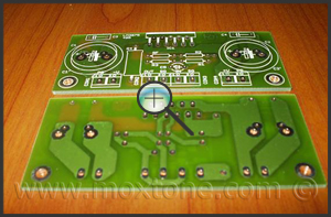
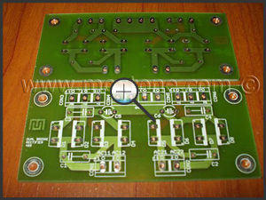
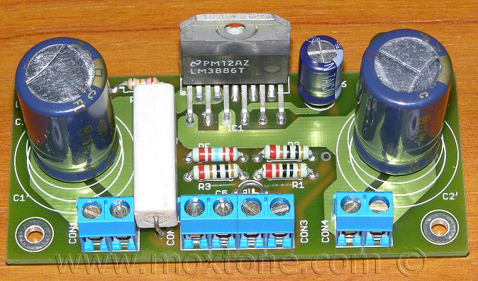
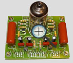
The volume potentiometer can be implemented as a standard potentiometer or, as in this case, stepped attenuator. It can be logarithmic or linear, ranging from 10 to 100 kΩ. The bare printed circuit board (PCB) is shown in Figure 2 whereas Figure 3 shows the assembled board, with R1, R4 and C5 omitted.
 |
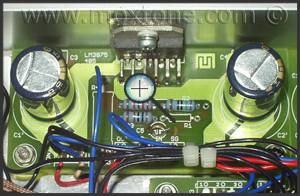 |
Figure 2 |
Figure 3 |
|
The amplifier can be used in the inverting mode, as well. Figure 4 shows the inverting circuit, where the input impedance is determined by the value of resistor R3. Therefore, you would want to choose an R3 value greater than 4.7 kΩ to avoid overloading the source to which the amplifier is connected. A common combination of values for R3/RF is 10k/220k. It follows that the optimum R1 value in this case equals the combined value of paralleled R3 and RF, which is 10k||220k=9k5 (or the closest value in the E96 resistor range). The voltage gain of the chipamp is determined by resistors R3 and RF, according to the following equation: Av = RF/R3, which gives Av = 22 The power supply circuit is shown in Figure 5. The power supply consists of a transformer with two independent secondary windings and two full-wave rectifiers that supply power to both amplifier channels. It is also possible to use a transformer with a center-tapped secondary winding. In that case, the center tap should be connected to one of the common ground pins/points (CON4, 5) whereas the two remaining taps should be connected in parallel to pins CON 1 and CON 2 (one tap to CON1-1 and CON2-1, and the other to CON1-2 and CON2-2). Furthermore, diodes D1, D3, D6 and D8 should then be omitted. |
Power supply parts list:
|
|
 Figure 4
 Figure 5
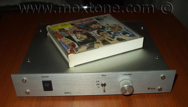
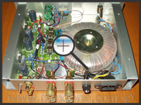
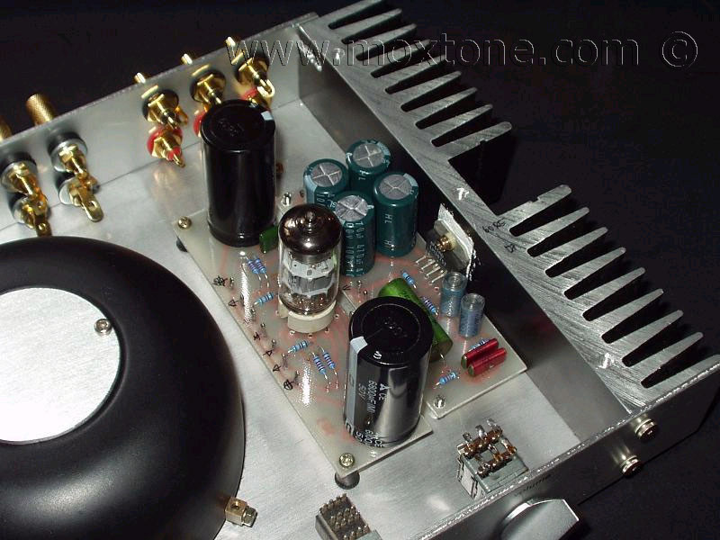
The power supply PCB, both before and after assembly, is shown in Figures 6 and 7, respectively.The characteristics of the transformer used in this amplifier are P=100VA and Vsec=2x24V, providing a voltage sufficient to drive two channels of a 30-Watt active speaker system. There are no dedicated heat sinks here because the entire aluminium chassis, which houses the amplifier, serves as a heat sink (Figure 7). However, if you decide that you wish to squeeze more power from the amplifier, you will surely need better cooling.
 |
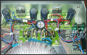 |
Figure 6 |
Figure 7 |
This project is simple to build and requires only basic knowledge of electronics, especially if prefabricated (commercially available) PCBs with silk screens are used. The most important thing is to make sure that all internal wiring is properly done. You may wish to start with the power supply and grounding wires first and pay extra special attention to the high-voltage(!) wiring – use well insulated wires and insulation jackets and do not forget to ground the amplifier chassis (if it is metal). All circuit grounds should meet at only one point (i.e. star ground) centered at the output of the power supply PCB (see the schematic below). Star-grounding will help you to avoid ground loops, which may lead to severe problems with hum and noise in audio amplifiers.
It is not a bad idea to add a switch on the rear of the amplifier, whereby the star (i.e. audio) ground could be connected to or disconnected from the chassis (i.e. safety) ground, as needed. The switch (i.e. ground lift switch) may help you to fight hum caused by external ground loops (between different devices in the system) by simply selecting the switch position with less (or no) hum and noise.
To connect the output of the amplifier to the speaker output terminals, a thicker (solid or stranded) wire should be used while high-quality shielded cables should be used for input signal wiring.
Given that this is a very simple and newbie-friendly amplifier, which has been successfully built many, many times with identical or very similar results, your satisfaction with the project should be guaranteed. As reported by thousands of DIYers from all over the world, the finished amplifier should sound quite good. Also, the concept is so minimalist that it leaves very little room for major mistakes so you should be able to freely indulge in fearless experimentation with different values and brands of capacitors, resistors, etc. and let loose that ‘crazy’ audiophile in you. The total cost of the project is a mere 100-odd EUR so heck, why not? (-v)
Related articles: |
|||
|
|||
|
|
||
COPYRIGHT NOTICE
This material is not public domain. It is provided for your personal use only and may not be reproduced, re-distributed, re-transmitted, copied or otherwise used in any form without the express written permission of the author. You may not upload this material to any public server, on-line service, network or bulletin board without the prior written permission of the author.
The use or copying of the contents of this page, in whole or in part, for any commercial purpose is expressly prohibited.