A JOURNEY INTO THE LEGEND: THE U47
(14 January 2014)
 |
||||||
|
 |
 |
 |
 |
||
 |
 |
 |
 |
 |
||
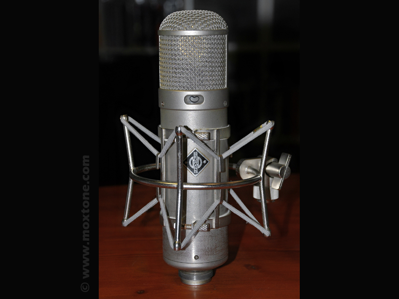
In the introductory part of the "Swank Frank Condenser Microphone" article, I stated (somewhat wistfully) that it was impossible to build a faithful copy of the Neumann U47 microphone without the following four vital components:
- VF14 vacuum tube,
- M7 or K47 microphone capsule from Neumann,
- Bv08 output transformer and
- appropriate metal housing.
 OK, but what if you had all these parts, I often wondered (click on the picture on the left to enlarge). Then you would have something that would not only look very similar to the original Neumann U47 but would also have to sound indistinguishable from the real deal, right? Incidentally, my curiosity was recently destined to be satisfied as, through a lucky set of circumstances and a very good friend of mine, I got hold of all of the above. And so began my journey into the mystique of the legend. It took quite a bit of my time and a lot of effort to complete and there were both challenges and revelations, as well as some inevitable myth-busting as I stumbled upon and tried to eliminate, or at least minimize, the weakear points of the original U47 design. What follows is the account of my findings. It is quite detailed and long (but hopefully not long-winded) so I have broken it into several sub-pages to make it easier for you to follow. You might want to brace yourself with a cup of coffee before you proceed, though.
Weak points of the original U47 design
1.1 Power supply - unregulated power supply
The U47 microphone is supplied with the DC voltage (Vb) of 105V and its current consumption (I) is around 40mA. The DC voltage is obtained through either batteries or the unregulated power supply connected to the AC mains voltage (Vm) of 110V (in the US) or 220V (in Europe). In the years following the Second World War (when the U47 was first introduced), this made perfect sense. Today, however, things are slightly different as the mains supply in Europe is gradually being standardized at 230V AC, while the mains supply in the USA is 120V. At first glance, the change may seem rather unremarkable until you realize that the unregulated power supply does not provide a constant supply voltage regardless of the mains voltage but quite the opposite: the output voltage from the power supply is in fact directly dependent on the mains voltage. Imagine, for example, that the nominal power supply voltage (Vb) is 105V and the mains voltage (Vm) is 220 V. The mains voltage normally fluctuates so at some point it leaps from 220V to 250V, which is still within permitted tolerance limits (in Europe, that is), and causes the voltage at the output of the power supply to increase by about 15-20V. Now, this is a different song and the one with a considerable potential of adversely affecting the proper operation of the microphone.
A partial solution to this problem would be to adjust the power supply for the nominal voltages (Vm) of 120V and 230V, respectively. However, your power supply would still remain sensitive to the mains voltage fluctuation within its allowable variation of 10%. Another solution would be to design a regulated power supply using modern semiconductor devices, where the output voltage would not be sensitive to mains voltage variations - a practical and neither particularly demanding nor costly endeavor.
But, truth be told, it has been claimed (and, at times, quite adamantly too) that the sound of such regulated power supplies is (subjectively) inferior to the original design. There have even been some attempts to rationalize these subjective reports in terms of differences between the harmonic structure of the residual noise of regulated power supplies, which is spectrally wideband, and unregulated power supplies, such as the original Neumann NG U47, where the harmonic structure is mostly limited to the fundamental tone and a few overtones of the mains voltage. However, the point remains moot. There is no way of knowing or guessing what the original U47 engineers would have done in this time and age because in their time semiconductors had yet to be invented and regulated power supplies with tubes were just too expensive and complicated to be a viable option. It was the time when tube and selenium rectifier diodes, huge chokes and metal/paper capacitors reigned supreme. Electrolytic capacitors were already available in the market but they had low capacity (by present standards) and poor durability.
 |
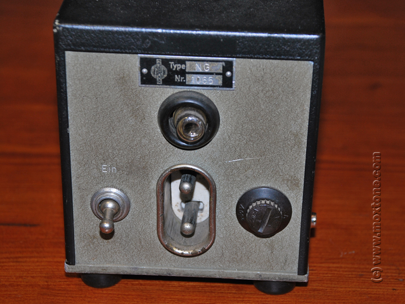 |
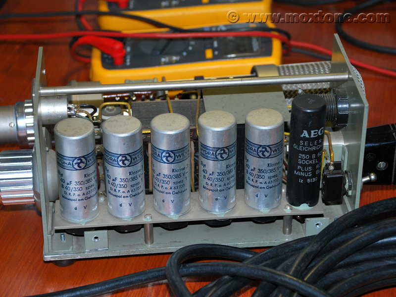 |
|
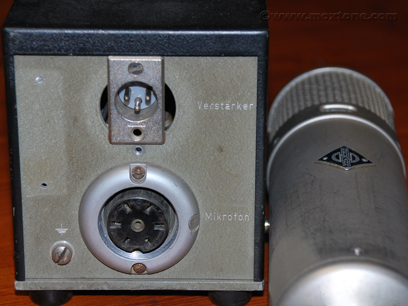
| Original Neumann U47 NG power supply (click to enlarge) | |
The solution proposed in this article falls somewhere in between the two options discussed above and it is a sort of controllable unregulated power supply, if you will.
1.2 Power supply – microphone
One of the major disadvantages of vacuum tubes is that, unlike semiconductors, they need to be heated to work. Their filament heating voltage (Vh) is typically low, ranging from 2.5 V to 50V or a bit more, and the current they draw ranges from 100mA up to several amperes. In addition, tubes require high anode voltage (Vb), beginning from 50V up to hundreds or thousands of volts when they are used as amplifiers. So, everyone with a modicum of knowledge on vacuum tubes already knows that power supplies for tube devices should have at least two (or more) supply voltages, which complicates the implementation to a certain extent, especially when it comes to mains transformer power supplies. The typical filament heating voltage (Vh) is 6.3 V or 12.6V for currents (Ih) in the range of several amperes, and the anode voltage (Vb) ranges from 250V to 400V for currents (Ih) in the range of several hundred milliamperes, depending on the type of application.
 The original U47 design uses a single power supply voltage (Vh-b) of 105V for the reason already explained earlier – so that the microphone could work with DC current sources in use at the time. The vacuum tube of choice is the legendary VF14 in its steel casing, whose heating voltage (Vh) is 55V and the heating current (Ih) is 50mA. Such unusually high heating voltage allows for a simple power supply, where the same high voltage source is used both as the anode voltage and the heating source. The heater is connected to the anode voltage via a series resistor (pictured right, click to enlarge), which lowers the voltage from 105V to 35-40V. The power dissipated on the resistor is pretty high, though. For the total power (P) consumed by the microphone P = Vb x Ib = 105 x 0. 04 = 4.2 W, as much as two-thirds is dissipated on the resistor while only the remaining third is actually used to heat the tube. Due to such high total dissipation, the microphone body gets rather warm, jeopardizing the long-term operation of the sensitive elements inside it.
You will often come across pictures from various recording studios clearly showing the U47 hanging upside-down. Besides purely practical (but occasionally also quite arbitrary) reasons, such as to allow the optimal positioning of the microphone in front of the recording artist, a key rationale behind this seemingly odd arrangement is that the upside-down position protects the capsule from excessive heat generated inside the microphone, allowing the warm air to flow up and away from the sensitive microphone capsule. As usual, there are those dissenting voices that argue that dissipation heat is actually beneficial to the longevity of the capsule because it reduces moisture inside the microphone, but I am not one of them.
In my opinion, tube dissipation alone generates just enough heat for the good health of the microphone so in my power supply design I keep the anode voltage and filament voltage separate. This brings the total dissipation (Pd) down to about 1.5W and prevents the microphone from getting uncomfortably and unsafely warm, at the same time allowing for a quick and easy replacement of the VF14 with any other suitable alternative, whose filament heating voltage (Vh) may be even, say, 6.3V.
1.3 Polar patterns
 The U47 microphone has two fixed polar characteristics - omnidirectional and cardioid – and a switch on the microphone body to choose between the two. In many situations, this is enough. However, the bi-directional pattern (also known as the 'figure-8') is sometimes very useful too (for recording with the MS technique, for example ) so the U48 microphone was introduced with the choice between the cardioid and figure-8 pattern. In order to realize the figure-8 pattern, it was necessary to lower the capsule's backplate polarization voltage (Vp) from 60V to 52.5V for the same anode voltage (Vb) of 105V. The lower polarization voltage has resulted in a slightly lower sensitivity of the U48 microphone in comparison with the U47 and an arguably slightly different character of the sound. Ah, the blessed art of compromise.
In my design, on the other hand, I have decided that the microphone must have any polar pattern available, from omnidirectional, cardioid, hypercardioid to figure-8, trade-offs be damned.
1.4 Spare parts
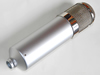
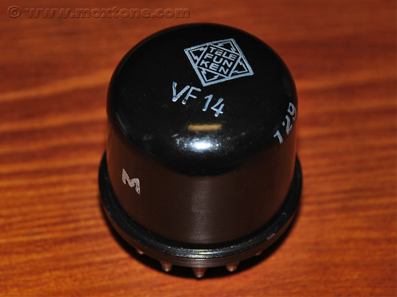 The U47 contains several critical elements that are quite expensive and difficult to come by, as already mentioned at the beginning of the article. The most difficult thing to obtain (and will be even more so in the future) is the very heart of the microphone - the VF14 vacuum tube. It is long gone out of production and the quantity produced in its hay-day was relatively small to begin with. Also, not all VF14 tubes were deemed suitable for the U47. Neumann had their own selection procedure to choose only the tubes which passed their test and measurements and which were then marked with the letter M (click to enlarge the picture on the right). Of course, if you happen to be in possession of a VF14 tube with no such marking, this does not automatically imply that it is no good for your U47 project because it may as well be that your fine specimen simply never got to the Neumann's test lab in the first place.
Anyway, the sad truth is that all tubes will wear out over time and all VF14 supplies will inevitably be depleted sooner rather than later. NOS VF14s will be impossible to source anywhere, no matter the price, so many U47 microphones will become practically useless in their original design.
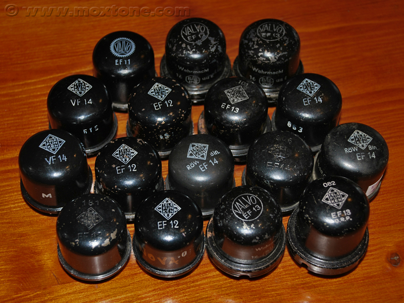
As VF14 prices have been skyrocketing for some time now, the number of alternative, more or less successful, solutions emerging on the market is on a slow but steady rise, be it FET amplifiers, nuvistors, other tubes... Personally, I am inclined to believe that the easiest solution is the one that also holds most promise for the near future: modification of all original U47s and their power supplies (including the separation of the anode and filament voltage sources) to accommodate more readily available and less-costly tubes such as the EF14, EF13, EF12, EF800... .
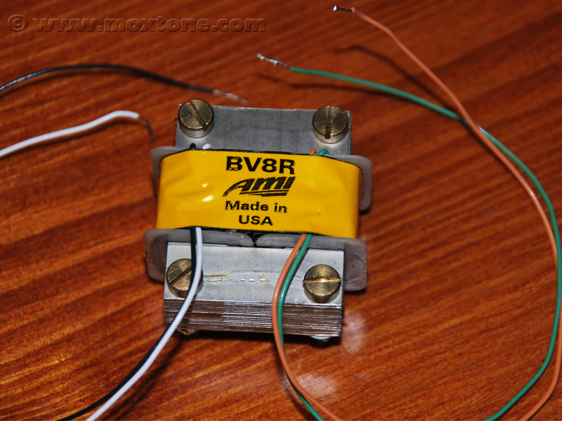
Another virtually unobtainable original element is the output transformer, whose core was once made from a special ferrous alloy that is no longer available from production. Fortunately, we now have a number of modern versions on the market, whose quality is either identical or very close to the original transformer. Also, defective transformers from original U47 power supplies can be recycled and given new life by simply rewinding them with new wire.
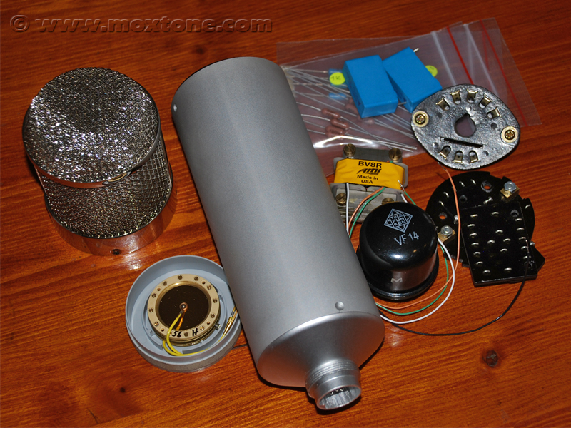
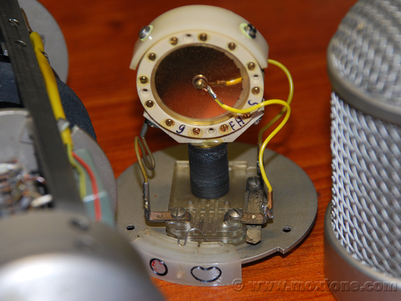 The third critical element is the microphone capsule (pictured left). It is subject to aging and deterioration from dust and moisture that over time and use leave a harmful deposit on the surface of the very thin and sensitive diaphragms of the capsule. At this point, it is becoming extremely hard to source the original M7 and K47 capsules in mint condition but the recent K47 production from Neumann has characteristics that are comparable to the old K47 and can be easily purchased. Alternatively, there is a number of well-established and highly qualified companies and individuals out there that specialize in reskinning defective capsule diaphragms, with very good results.
Given the above, it is clear that the VF14 tube poses the biggest technological challenge to the maintenance of existing U47 microphones or the construction of their duplicates. This is why I have configured my design to allow for an easy installation of other, more readily available tubes mentioned earlier in the text.
mU47 microphone design
2.1 Schematic
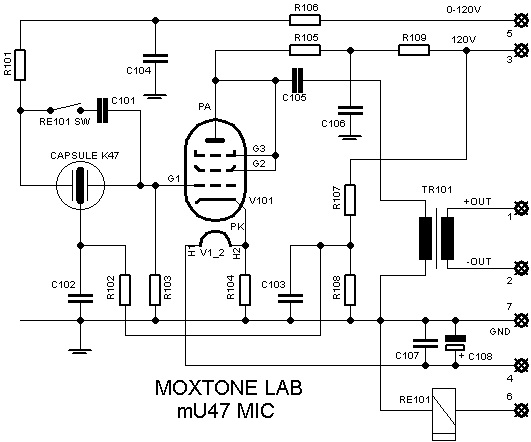
The design of the mU47 microphone is shown below:
Parts list:
| R101 | 1GΩ | C102 | 22nF/400V MKC | |
| R102 | 1GΩ | C103 | 22nF/400V MKC | |
| R103 | 1GΩ | C104 | 22nF/400V MKC | |
| R104 | 29Ω | C105 | 1uF/250V MKP | |
| R105 | 127kΩ | C106 | 1uF/250V MKP | |
| R106 | 1MΩ | C107 | 100nF/63V | |
| R107 | 1MΩ | C108 | 10uF/63V | |
| R108 | 1MΩ | TR101 | BV08 AMI | |
| R109 | 1MΩ | RE101 | 5V single pole latching | |
| C101 | 1200pF/400V MKC | V101 | VF14 |
The filament heating voltage for the tube is supplied separately from the anode voltage through Pin 4 of the input connector. C107 and C108 capacitors provide additional smoothing of the voltage. The power supply design also allows for the adjustment of the filament heating voltage to a default value regardless of the actual mains voltage.
The anode voltage (Vb) here is 120V, which is slightly higher in comparison with the original U47 where it is 105V. The voltage value of 120V was chosen so that it may also be used to polarize the capsule. The fixed electrode of the capsule (backplate) is polarized with the voltage of 60V (recommended value for the M7 and K47 capsules) and the polarization is accomplished with the use of a voltage divider consisting of R107 and R108 resistors, C103 and C103 smoothing capacitors and R102 polarization resistor. The moving diaphragm at the front of the capsule is at the zero potential, while the one at the back is polarized with the variable voltage supplied by the power supply via R101 and R106 resistors.
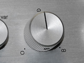 The variable polarization voltage is used to set the directivity of the microphone and it can be adjusted through 11 different settings (pictured left). When the voltage is set to 0V, the polar pattern is omnidirectional. As the voltage increases, the pattern becomes wide-angle cardioid so when it reaches 60V, we get the full cardioid pattern. By further increasing the polarization voltage, the pattern becomes hypercardioid and when the maximum voltage of 120V is applied, we have the figure-8 polar pattern. As a result – and unlike the original U47 design, whose polar characteristic can be either omnidirectional or cardioid – this design provides considerably more options and hence much better recording flexibility.
Such a variable polarization design has one teeny-tiny flaw, though, which the most fervid fans of the original U47 would certainly not fail to point out. Specifically, when the microphone is set to the cardioid polar pattern and the back diaphragm of the capsule is polarized with 60V, which is also the polarization voltage of the microphone's backplate (i.e. the fixed electrode) so the back diaphragm of the capsule cannot contribute to the useful signal, the back diaphragm still generates about 2-3dB of noise. So, in order to eliminate the 'flaw', I have added a relay to my design. It is activated remotely from the power supply and its role is to disconnect the back diaphragm of the capsule when the variable polar pattern is not needed.
Of course, the use of relays for switching polar patterns is not a new idea. The biggest challenge, however, is how to design and implement the relay to prevent it from adding noise and degrading microphone operation. What's worse, the relay must be physically placed as close as possible to the capsule and the vacuum tube in the high-impedance part of the microphone, which is very sensitive to any outside sources of electromagnetic pollution such as the relay would be in this sort of application. To ensure that the relay does not cause any problems and interferences, we now come to the originality of this whole idea – the use of a latching relay. The latching relay here is set to one of the two stable states using positive and negative impulses and once the desired state is attained, the relay no longer needs to be powered during operation (unlike regular relays). This allows us to eliminate any negative effects of the relay's electromagnetic field on the most sensitive parts of the microphone because the electromagnetic field is created only during the relay setting procedure and once the relay is set, the electromagnetic field is shut off.
To set the vacuum tube to the approximately same operating point as in the original U47 (Ia= 0.5 mA, Va=35V, Vg=-1.1 V), allowing for the increased anode voltage (Vb) of 120V, R105 anode resistor needs to be increased from 100kΩ to 127kΩ. The increase in the value of R105 decreases the load on the tube so the tube operates in a more linear regime, which brings us to yet another argument in favor of increasing the original U47 anode voltage.
The operating point of the VF14 is determined by the negative bias (Vg) of the control grid. The negative bias is in turn determined by the current flowing through R104 resistor, which is also the filament current of the tube. This particular implementation of the so-called fixed bias is the same as in the original microphone, the only difference being that in this design it is possible to adjust the filament voltage and current via the power supply unit.
Resistors R107 and 108 have the same value and serve as the voltage divider whereby the backplate polarization voltage (V) of 60V is extracted from the anode voltage (Vb) of 120V. Naturally, any change in the anode voltage will change the backplate polarization voltage and consequently the tension of the front diaphragm, which may in turn alter the frequency characteristic of the microphone.
2.2 Electonics and hardware
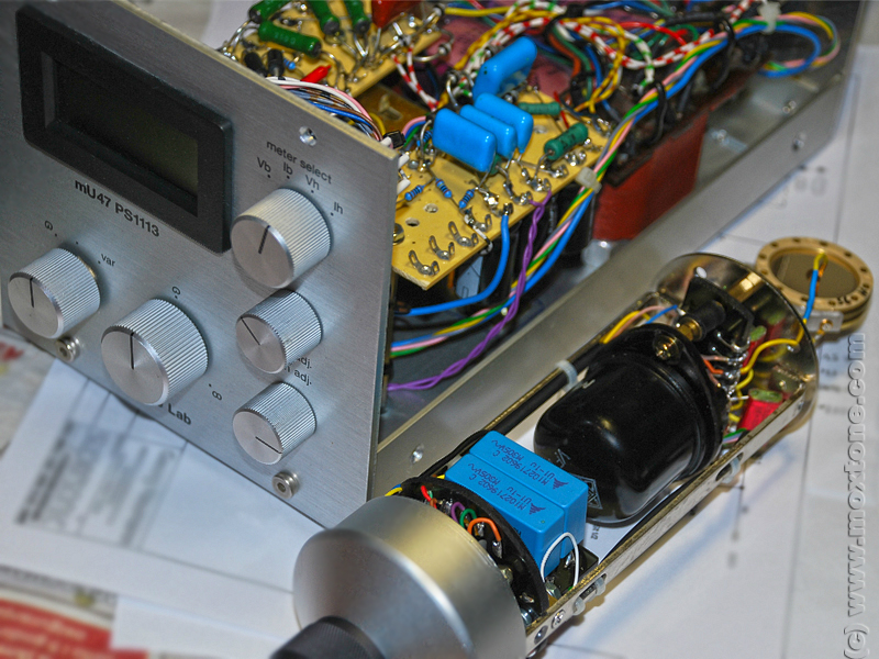
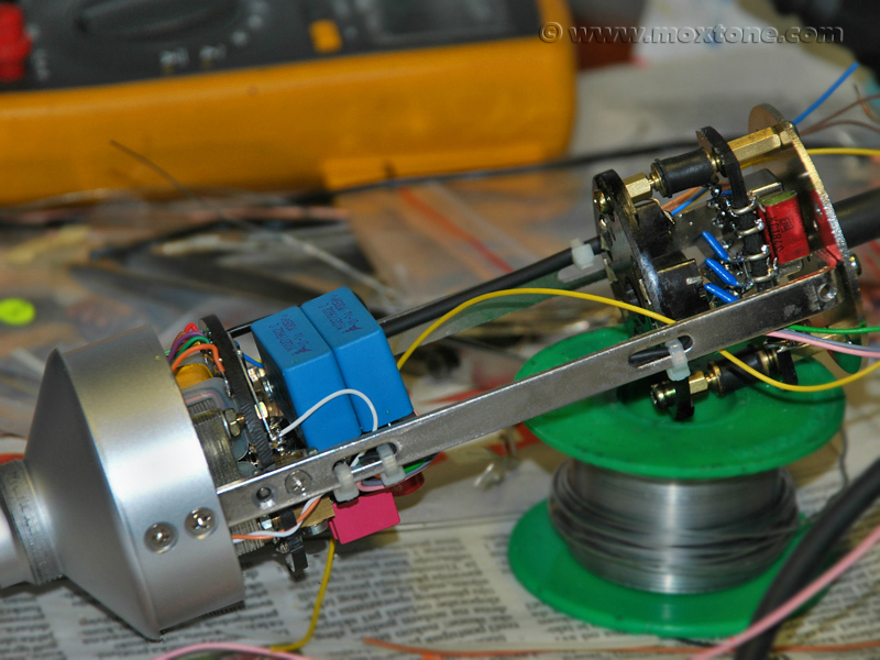
The microphone is housed in the same body as the earlier Swank Frank project. The body is available from Equinox Systems and it offers good value for money although there are more upscale options out there on the market if you are willing to bear the price. The K47 capsule is mounted onto the capsule holder that was purchased, like the Bv08 output transformer, from AMI.
 |
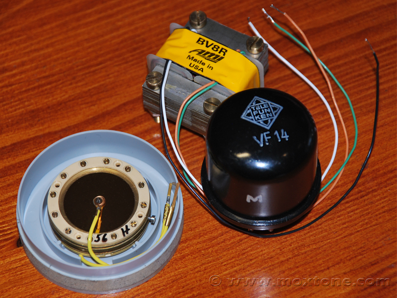 |
Output transformer (left and right), K47 capsule and VF14 tube (right) |
|
The rubber part of the purchased capsule holder (i.e. shock mount post) proved insufficiently stiff, especially in comparison with the original holder, and caused the capsule mounted onto it to slightly wobble and vibrate with movement. The issue was solved by coating the holder with two layers of transparent heat shrink tubing, which made it snug and tight enough to prevent any noise from mechanical vibration.
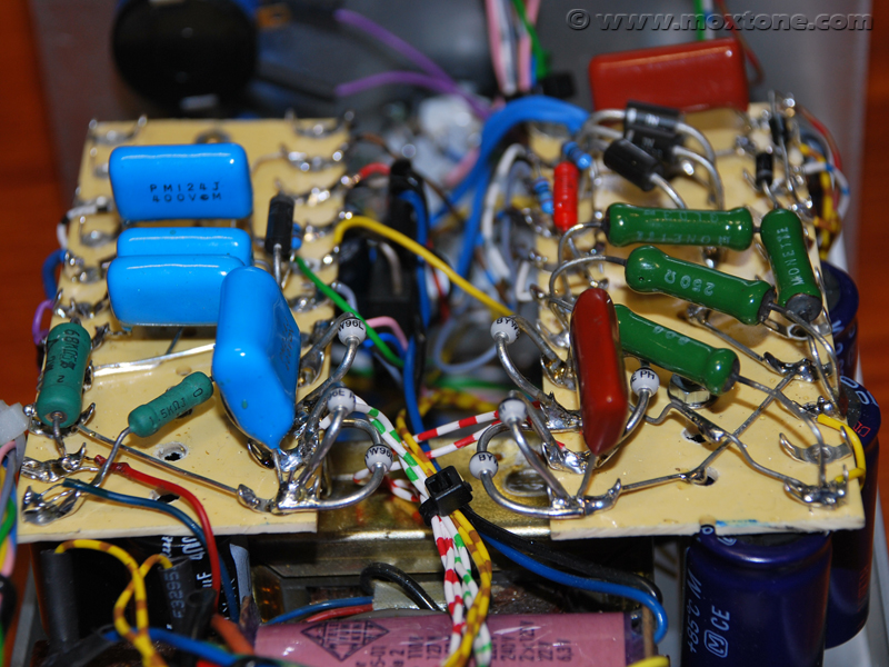
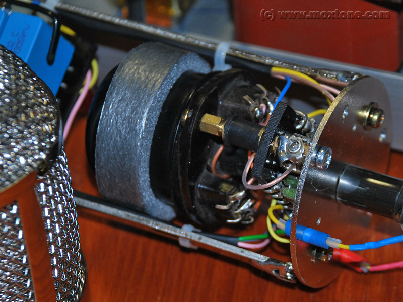 The electronic parts of the microphone are placed on three acrylic boards with solder pads made from 1mm-thick silver-plated copper wire. Acrylic was chosen because of its very high electrical insulation and good mechanical properties. After all, the original U47 uses a similar approach. The tube socket is elastically mounted inside the housing using rubber standoffs while the tube itself has a damper ring around it, made from central heating insulation material (pictured right, click to enlarge). In this way, the tube is elastically suspended inside the enclosure, which helps to reduce the risk of microphonics and protect the tube from mechanical vibrations of the microphone body.
All parts used in the project are standard quality, from Dale resistors to MKC and MKP capacitors. The internal wiring is made from OFC multistrand wires from Mogami multicore cables.
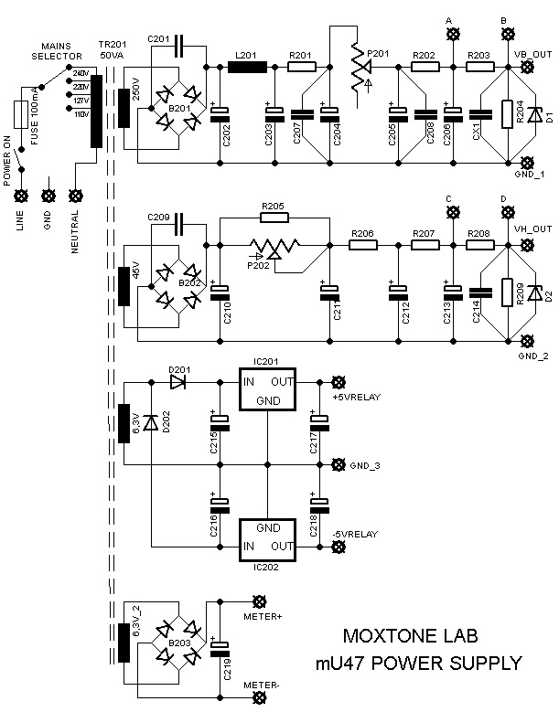
mU47 power supply design
The power supply for this design needs to generate 4 different voltages:
- voltage of 120V and current of up to 1mA for the anode voltage and capsule polarization;
- voltage of 40V and current of 50mA for filament heating;
- voltage of +/- 5V and current of 200mA to switch the latching relay, and
- unregulated voltage of 9-12V to power the control meter.
The power supply layout is shown in the schematic below:
Parts list:
| R201 | 39kΩ/1W | C209 | 100nF/400V MKP | |
| R202 | 68kΩ/1W | C210 | 1000uF/100V | |
| R203 | 100Ω/1% | C211 | 1000uF/100V | |
| R204 | 1MΩ/1W | C212 | 1000uF/100V | |
| R205 | 500Ω/5W | C213 | 1000uF/100V | |
| R206 | 250Ω/5W | C214 | 100nF/400V MKP | |
| R207 | 250Ω/5W | C215 | 1000uF/25V | |
| R208 | 1Ω/1W/1% | C216 | 1000uF/25V | |
| R209 | 10kΩ | C217 | 10uF/25V | |
| P201 | 100kΩ/2W/multiturn | C218 | 10uF/25V | |
| P202 | 500Ω/2W/multiturn | C219 | 1000uF/25V | |
| C201 | 100nF/400V MKP | D1 | 150V/5W | |
| C202 | 33uF/400V | D2 | 3x51V/5W zener in parallel | |
| C203 | 33uF/400V | D201,202 | 1N4001 | |
| C204 | 33uF/400V | B201,202 | 4xBYV96E | |
| C205 | 33uF/400V | B203 | 100V/1A | |
| C206 | 33uF/400V | L201 | 47H/5mA | |
| C207 | 100nF/400V MKP | IC201 | 7805 | |
| C208 | 100nF/400V MKP | IC202 | 7905 |
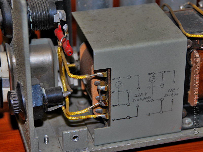
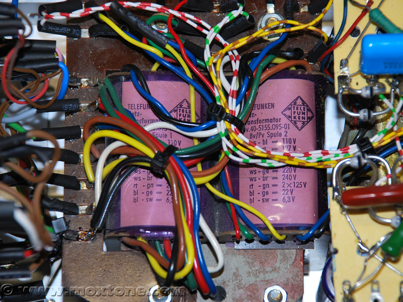
The building block of the power supply unit is the power transformer (below on the right) culled from a vintage Telefunken radio. It has an output power of around 50VA and all the necessary secondary windings (250V, 45V, 2x6.3V), as well as taps on the primary side of the transformer to cater for different mains voltages (110V,117V, 220V and 240V).
 The anode voltage, which is also used for capsule polarization (as mentioned earlier), is obtained from Power Supply 1 (PS1). It is a standard unregulated LRC power supply that can be found in many tube preamplifiers and amplifiers, and consists of the LR and RC smoothing filters and a multiturn potentiometer whereby the output voltage can be set to the desired value.
The filament voltage is obtained from Power Supply 2, whose topology is identical to that of PS1, except that its resistors and capacitors are rated for higher current that this power supply needs to generate. I could have approached these two power supplies differently, using modern high-voltage regulators (LM783, for instance) as I had previously done in the Swank Frank project. However, in this case, I found it more advantageous to stick to the original U47 topology all the more because I was able to address its shortcomings by adding a potentiometer and a control meter module to allow for the precise adjustment of the output voltage.
Power Supply 3 is used to power the latching relay, which requires the positive and the negative voltage of 5V. The power supply consists of one half-wave rectifier and two, positive and negative, 5V regulators.
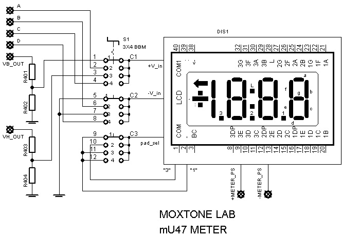
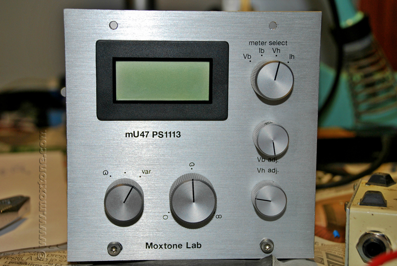
Power Supply 4 gives power to the digital control meter, which measures and displays the voltages and the currents generated by Power Supplies 1 and 2. In order for the meter to measure all the voltages and currents, a separate galvanically isolated power supply like this one is needed. The meter display is the standard 3.5 seg. one, with the rated sensitivity (Vin) of 200mV and the internal resistance (Ri) of 10MΩ. Its circuit is given below.
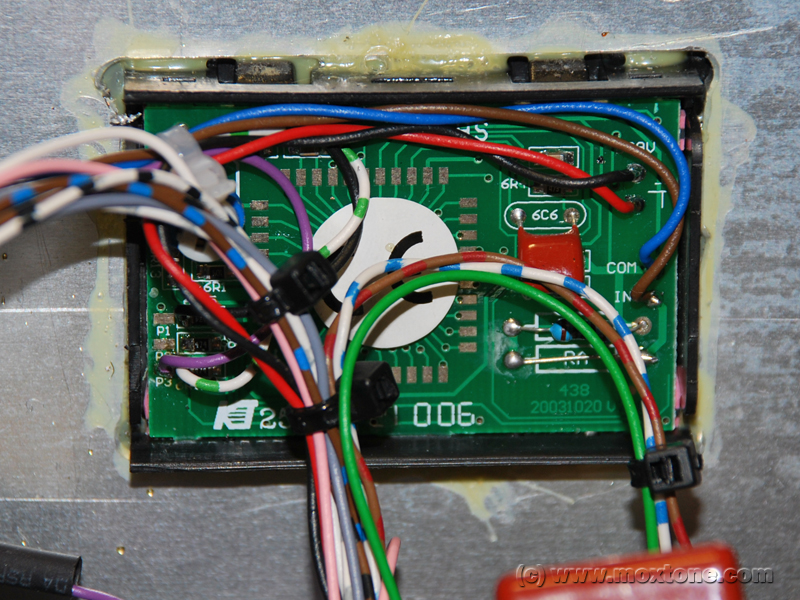 |
 |
Control meter |
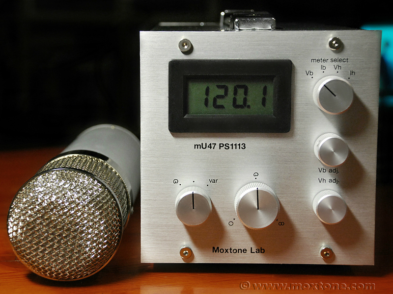
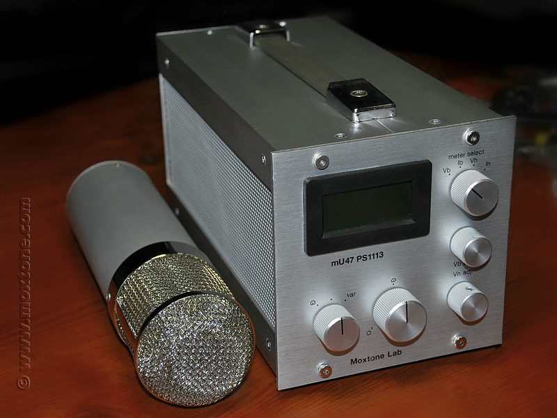
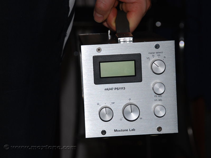
|
The whole power supply unit is housed in an aluminum enclosure with side vents for cooling, and its dimensions are 130x130x250mm. On the front plate of the enclosure, apart from the control meter display mentioned above, there are following potentiometers and switches:
- S1 switch for the selection of parameters measured by the control meter, namely: anode voltage (Vb), anode current (Ib), filament heating voltage (Vh) and heating current (Ih);
- potentiometer for the fine adjustment of the anode voltage (Vb) to the value (Vh) of 120V (in doing so, the total current (I) should be approximately 0.85 mA; the total current is the sum of the tube's anode current and the currents of the three voltage dividers, whose total consumption is 0.3mA);
- potentiometer for the fine adjustment of the filament heating voltage (Vh) to the value of 36V for the heating current (Ih) of about 40mA;
- 11-position switch for the precise control of the polar pattern (from omnidirectional through cardioid to figure-8), based on the circuit used in the Swank Frank project;
- 3-position switch for the selection between the variable and the fixed polar pattern; during microphone's operation, the switch is in the middle neutral position and it can be flicked (briefly, for no more than a second) either to the left or to the right to set the desired polar pattern.
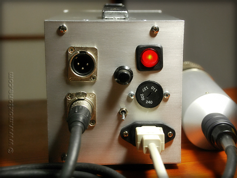
At the rear of the power supply unit, there is a 7-pin XLR connector for the microphone cable connection, 3-pin output XLR connector for the audio signal connection to the recording console, euro connector for the mains supply, 100mA fuse, groundlift switch, power supply turn on/off switch and a mains voltage selection switch.
In Europe, where the nominal voltage (V) is 230V, one can switch between 220V and 240V, depending on the actual mains voltage, whereas in the US, the choice will be between 110V and 127V.
 |
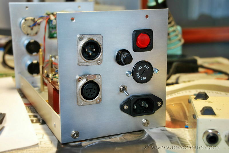 |
Power supply unit, front and rear view |
|
Conclusion
The purpose of this article was to present a variant of the famous U47 microphone that would keep all of its legendary strengths and character but, at the same time, minimize or altogether eliminate its outdated features so as to make it as practical and usable as possible in the modern-day environment that we live in. And I believe that this purpose has been achieved. The mU47 microphone was thoroughly tested under different conditions and due to its adaptive power supply, it was always possible to set it up to behave and measure exactly the same regardless of any differences in the mains voltage. This means that, unlike the original design, the mU47 microphone will sound identical in any location and in any situation. The constant monitoring of all vital parameters via the control meter display gives complete control of the microphone's operation and enough leeway to anticipate and properly respond to any problems or circumstances that may arise. Lastly, but quite importantly, when the microphone is on and the tube is fully heated, both the anode voltage and the filament heating voltage remain stable while the body of the microphone does not get even faintly warm to the touch.
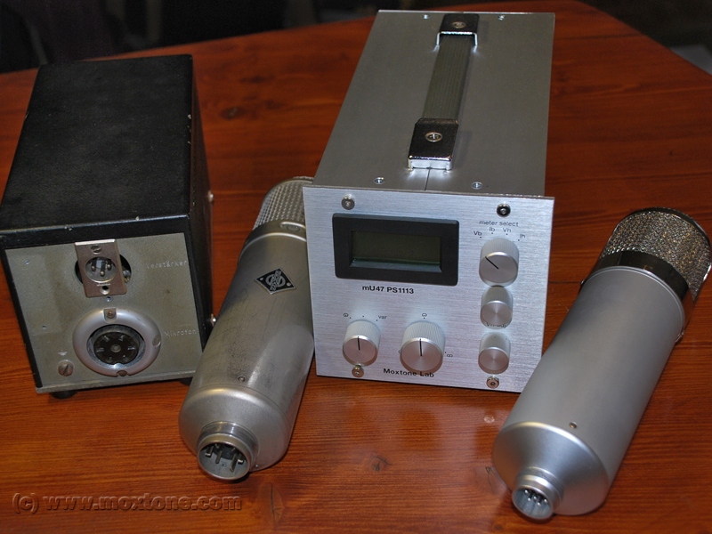 The sound of the microphone was directly compared with the sound of the original U47 at hand. The only audible difference was the cleaner sound of the mU47 whereas the timbre and the overall character of the original U47 sound were rendered accurately and with great authority in this new version.
The polar pattern selection feature works as envisioned, making the microphone a much more versatile recording tool than it was originally made to be.
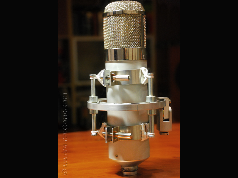
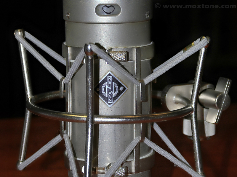
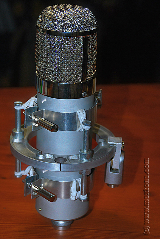 Also, the mU47 is not sensitive to mechanical vibrations. My DIY shock mount proved to be sufficiently stable and provided solid support (pictured on the right).
Finally, the power supply design presented here can be relatively easily modified in the course of no more than a day or so to work with some other vacuum tubes, such as the EF14, EF12, etc., all at a cost of no more than USD50.
The U47 microphone from Neumann has become a sort of the Holy Grail for professional sound and recording engineers and artists all over the world so I suspect that the approach presented here might get a flame or two from purists and diehard keepers of the doctrine on account of the blasphemous nature of the very idea. However, I do hope that many of you reading this article will manage to keep your minds open and see the project as it is intended - a very versatile and flexible recording tool and a source of some quite useful ideas. Who knows, some day this project may as well end up being your only ray of hope to save the beloved U47 when the VF14 tube wears down and a new one is either to be found nowhere, search heaven and the seven seas, or it costs your first newborn child.
And maybe the project will draw out the courage necessary for you to finally get to grips with that tired old power supply in its losing battle with pesky mains voltage swings. In that case, you may also wish to read the article that follows (Part 2), which will give you a more detailed insight and a new view on some old dogmas and myths surrounding the original U47 power supply and all its quirks.
In the final article of the series, entitled "The output characteristics of the VF14 and its substitutes", you will find a battery of comparative tests on the VF14, EF14, EF13 and EF12 tubes with a brief review of their potential for use in microphones like the one we have been discussing here.
Related articles: |
|||
|
|||
|
|||
COPYRIGHT NOTICE
This material is not public domain. It is provided for your personal use only and may not be reproduced, re-distributed, re-transmitted, copied or otherwise used in any form without the express written permission of the author. You may not upload this material to any public server, on-line service, network or bulletin board without the prior written permission of the author.
The use or copying of the contents of this page, in whole or in part, for any commercial purpose is expressly prohibited.