POWER AMPLIFIER WITH IC LM3886
(16 January 2006)
Croatian version
The characteristics of this IC audio amplifier are quite similar to those of the previously discussed LM3875. The main differences are the external control of the “mute” function and a bit more current that the LM3886 will provide. Due to its higher output current, this IC is more suitable for power amplifiers designed to drive subwoofers or, more generally, low-impedance speakers. The amplifier’s schematic is shown in Figure 1.
 Figure 1
Parts list:
| R1 | 10 kΩ |
| R2 | 1 kΩ |
| R3 | 1 kΩ |
| R4 | 0.1 Ω/3-5W |
| R5 | 22 kΩ |
| Rf | 22 kΩ |
| C1, C2 | 1000uF/50V |
| C3, C4 | 220nF/50V |
| C5 | 47 uF/50V |
| C6 | 100 uF/50V |
| IC | LM3886 |
All the comments that were made in the LM3875 article regarding parts selection, values and possible configurations also apply here. The power supply schematic given in the LM3875 article can be used here, as well. The characteristics of the transformer for a mono version of the amplifier are P=100V, Upr=230, Usec=2x24V. For a stereo version, the power of the transformer should be doubled.
The LM3886 is in practice often used in parallel or bridge configurations. Two ICs in parallel mode give a higher maximum output current, which enables us to get more power from the amplifier (over 100W) at full output voltage into a 4-ohm load. Bridge mode increases the usable output voltage range of the amplifier so it can be used with high impedance speakers (8 ohms or more). Also, it is possible to combine two paralleled amplifiers in bridge mode with another pair of paralleled amplifiers. The power of such an amplifier, consisting of 4 LM3886’s, may exceed as much as 200W, depending on the supply voltage and cooling method.
Cooling is extremely important here. The efficiency of the amplifier is slightly over 50%, which means that the amount of power dissipated as heat roughly equals the output power; thus a 50-Watt amplifier, for example, will have a maximum power dissipation of about 50W. Therefore, this project requires large heat sinks (about 0.5 °C per 1W) unobstructed for proper air flow. The IC should be electrically insulated and mounted to the heat sink.
Capacitors C1 and C2 shown here have the minimum value required to ensure reliable amplifier operation. However, if the amplifier will be used to drive some demanding speakers or subwoofers, the value of these capacitors should be increased to 4700uF or more, with the same rated voltage.
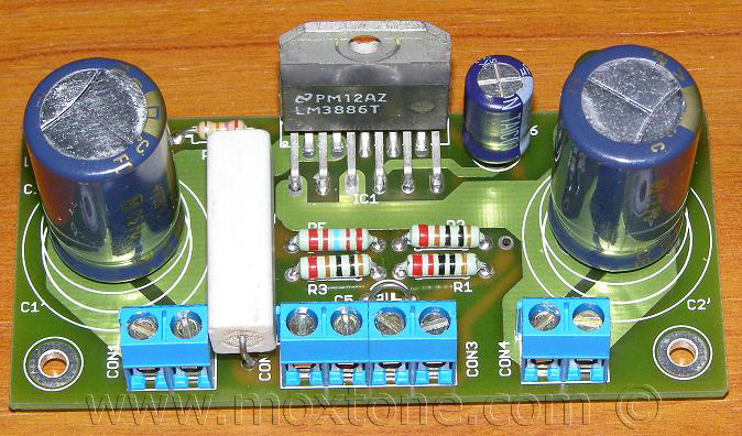
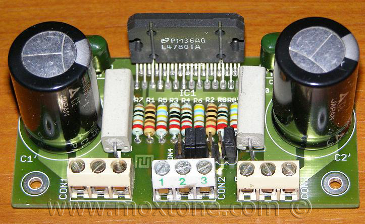
For all additional data on the LM3886 , please refer to the Texas Instruments’ website (note: in 2011, National Semiconductor was acquired by TI). The measurements of this particular amplifier are entirely consistent with the results published by the manufacturer. The bare LM3886 PCB is shown in Figure 2 below.
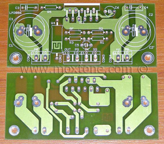 Slika 2
Related articles: |
|||
|
|||
COPYRIGHT NOTICE
This material is not public domain. It is provided for your personal use only and may not be reproduced, re-distributed, re-transmitted, copied or otherwise used in any form without the express written permission of the author. You may not upload this material to any public server, on-line service, network or bulletin board without the prior written permission of the author.
The use or copying of the contents of this page, in whole or in part, for any commercial purpose is expressly prohibited.