HIGH-QUALITY STEPPED ATTENUATORS FOR LESS
"High-Quality Stepped Attenuators for Less" is a sequel to a previously published article of mine on "Load Impedance and Stepped Attenuators" (AudioXpress 06/05). "High-Quality Stepped Attenuators for Less" was originally published in the 2006 October issue of AudioXpress. The .zip file of the English version of "Load Impedance and Stepped Attenuators" can be dowloaded here (.doc and Excel files). The Croatian draft of "Load Impedance and Stepped Attenuators" was released here (NB: the Excel calculator can also be downloaded from the official AudioXpress web site).
Introduction
Let me get one thing straight right away: This is not a ‘Complete Guide to Secrets of Producing High-Quality Attenuators for One Thin Dime in the Comfort of Your Own Home’. My intention here is to show you how to make an attenuator that would be perfectly customized for your application and design requirements, without spending near as much money as you would for buying that standard stepped stuff from your local retailer. How little money you are going to actually spend will depend on several things that you would need to consider very carefully before you get that soldering iron of yours hot and ready. You will thus have to choose the attenuator type, decide on the number of steps you need, select proper resistors for the job and define the attenuator’s nominal resistance.
Common types of stepped attenuators
A serial-type attenuator (Figure 1) can be used as a direct substitute for a common potentiometer. It consists of a chain of resistors connected in series. The number of resistors in the chain, as well as the number of switch steps, will depend on the attenuator resolution desired. The main disadvantage of this type of attenuators is that all resistors are in the signal path at one time, each of them detracting somewhat from the quality and overall performance of the attenuator.
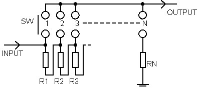 Figure 1: Serial-type attenuator
A ladder attenuator (Figure 2) overcomes this major shortcoming of the serial type by utilizing one switch with two resistor layers per channel. As there are only two resistors in the signal path, resistor noise is negligible. On the other hand, its comparative disadvantages include two switch contacts and twice as many resistors needed.
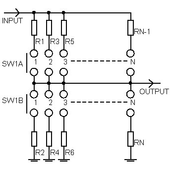 Figure 2: Ladder attenuator
A shunt version (Figure 3) performs like a ladder attenuator, only with fewer resistors. It is not as popular as series and ladder type attenuators, mostly due to its variable input impedance.
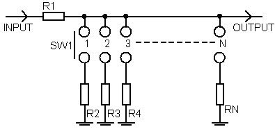 Figure 3: Shunt attenuator
Number of switch steps
The number of steps or switch positions will depend on the attenuator resolution desired. It has been experimentally established that a minimum resolution of 2dB per step in the attenuation range you use the volume control most often will do. In other words, you do not need fine control across the entire attenuation range, particularly not at the bottom of the volume control range (low volume levels) where attenuation is highest, so the attenuation per step may be set to 3 dB value or more. Assuming that the overall attenuation range is 60 dB, a 24-position switch should provide a sufficiently precise signal-level control. Attenuators with 12 steps are less commonly used because the steps are too far apart to provide adequate resolution. On the other hand, commercially available switches with more than 24 steps (typically 32 or 48) are too expensive to warrant their use in most DIY projects.
What resistors to use
The principal factor you need to take into account when selecting the right resistors is their precision because resistor precision affects attenuation accuracy per step and channel-to-channel signal level tracking. As a general rule, you should go for 1% precision resistors for 24-step attenuators, or better if you are building a more complex attenuator design.
Since the signal path passes through resistors, the more resistors you use the higher possible resistor noise in the signal path. However, practical experience shows that resistors with lowest noise characteristics are not necessarily the best-sounding to our ears, due to individual differences in psychoacoustic aspects of the human hearing system or, simply put, due to our different individual tastes. It is necessary, therefore, that you try out different brands available in the market and stick to the one you feel to be best suited to your sonic preferences and application. Cost-wise, better-sounding resistors are usually more expensive. For instance, standard 1% metal-film resistors can cost as little as 0.1$ a piece while, on the other hand, tantalum resistors typically cost up to 5$ a piece, which can obviously make quite a huge difference and add up to significantly more than your budget will stand.
Attenuator’s nominal resistance
In my previous article, I discussed the effect of the input impedance of amplifiers/preamplifiers on the resolution of your attenuators. The input impedance of an attenuator will also depend on the source signal. As a rule of thumb, the nominal resistance of the attenuator should be between 10 and 100 kohm. This is not critical where the input impedance of the signal source is low (100 ohm) and that of the amplifier is high (100 kohm).
As regards induced noise levels and frequency linearity, it is always better to use the lowest possible value whereas the highest possible value will make the load easy on the source.
Choosing the right attenuator
If you tend to play your audio system at a limited range of volume levels (e.g. moderate), you do not really need a volume potentiometer with 24 positions. In that case you may wish to consider building an attenuator with fewer steps and a 2dB per step attenuation curve, where you would be able to fine-tune the steps to the sound levels that cater best to your listening preferences. For most people, that range is typically between -20 and -10dB and that is where your attenuator should perform best. Outside that attenuation range, when playing at low volume levels where you do not want your music to be too intrusive (e.g. soft background music), cheaper resistors will do just fine. Besides, the step from active to passive listening is a relatively big one, 20dB or more. For that reason, broadcast consoles have a special dimmer switch that attenuates the signal by 20dB so you do not have to use an attenuator at all.
In the next part of this article, I will show you how to build and optimize a good-quality serial-type attenuator with dimmer function and a 12-step make-before-break switch.
Implementation
One such implementation is shown in Figure 4. SW1 is a two-pole switch (for two channels, you will need a four-pole one) with two positions that allow you to choose an attenuation value of between 0 and 24dB. It can be either a push-button or toggle switch, and it functions as a dimmer.
SW2 is a one-pole (for stereo, you should use a two-pole unit), 12-position make-before-break-type rotary switch. It allows you to adjust the volume level in 12 steps of 2dB each, providing an attenuation range of 0dB to -22dB when SW1 is set to 0dB. When SW1 is set to -24dB, the attenuation range of SW2 will be between -24 and -46dB. Thus, we get a total attenuation range of 46dB in 2dB steps.
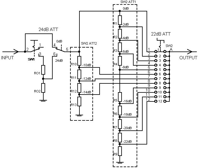 Figure 4: Optimized serial-type attenuator
A first glance reveals a somewhat untypical implementation of the series attenuator SW2 resistor network. The attenuator in fact consists of two series attenuators – SW2 ATT1 and SW2 ATT2. SW2 ATT1 circuitry comprises resistors R1 through R8, covering the attenuation range from 0 to -8dB and from -16 to -22dB. SW ATT2 is made up of resistors R10, R11, R12 and R13, with the attenuation range from -10 to -14dB.
The total attenuation range is thus split into two segments – the comparatively large range, which is used less often (SW2 ATT1), and the smaller but, I should assume, the most frequently used attenuation range (SW2 ATT2). Here is a money-saver tip for you frugal DIYers: do not throw your hard-earned cash on high-quality resistors for the attenuation range which is of only secondary importance for your purposes (i.e. SW2 ATT1) when you may do just as well with standard and cheap metal-film ones. SW2 ATT2 used here is quite similar to ladder-type attenuators; there are two switches and only 4 resistors in the signal path for the three most frequently used attenuation steps!
Calculating the value of individual resistors
We start off by defining the attenuator’s nominal resistance. In our example, where the output resistance of the signal source is low (up to 100 ohm) and the input impedance of the amplifier exceeds 100kohm, the attenuator’s nominal resistance is 11 kohm. Naturally, you may use any other values you wish for your attenuators. The value of each resistor is then calculated using the spreadsheet published in (issue of AudioXpress). First, we calculate the values of resistors R01 and R02 for the fixed attenuator, which is loaded with SW2 attenuator whose nominal resistance is R=11kohm. We enter the value of 11 kohm in the Rina field. In the attenuation field, we enter only 24dB. The figures we get for R1 and R2 are the values of our resistors R01 and R02 (Figure 5).
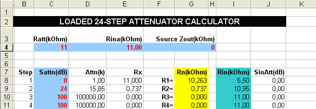 Figure 5: Spreadsheet results for SW1
We now move on to calculating the values of each resistor in the first attenuator (SW2 ATT1). Its nominal resistance is 22 kohm (the two attenuators are connected in parallel), Rina is 100 kohm or more and the attenuation step values are 0, 2, 4, 6, 8, 16, 18, 20 and 22 dB. The resulting figures are the values of resistors R1 through R9 (Figure 6).
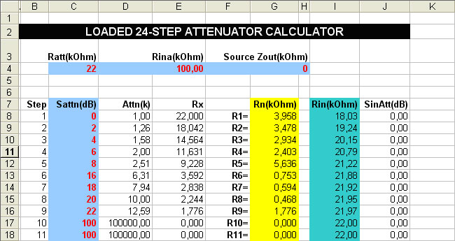 Figure 6: Spreadsheet results for SW2 ATT1
The same calculation procedure is repeated to find the values of resistors R10 through R13 but this time entering the attenuation step values of 10, 12 and 14 dB (Figure 7) in the table.
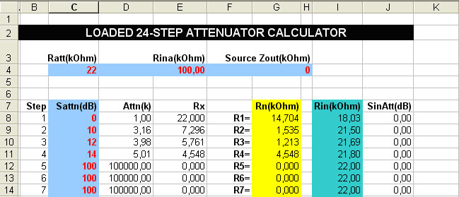 Figure 7: Spreadsheet results for SW2 ATT2
Of course, you may make whatever modifications and adjustments you may require for your particular project. Thus, you may choose a different nominal resistance for your attenuator, a different per-step resolution, a different attenuation range where you want your attenuator to perform at best (i.e. the one requiring more expensive resistors), etc. To obtain a resolution of 2.5 dB per step, for example, you will need an attenuator with a maximum attenuation of 23x2.5=57.5 dB and SW1 attenuation of 12x2.5dB=30dB.
Practical example
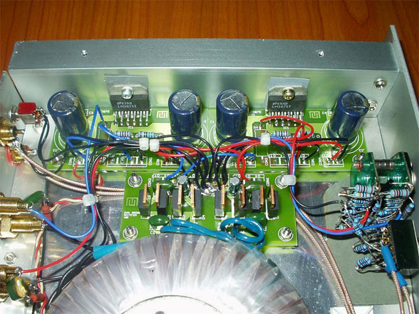
Figure 8 shows a practical implementation of the attenuator in a low-power IC-based amplifier using the IC LM3875. The resistors in the amplifier circuitry and that part of the attenuator which is most frequently in use during operation are tantalum ones while those used in the rest of the attenuator are standard 1% metal-film resistors.
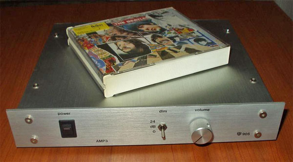 Figure 8: Low-power amplifier with attenuator
SW1 is a standard four-pole toggle switch with gold-plated contacts while SW2 is an average quality two-pole make-before-break rotary switch with 12 positions (Figure 9).
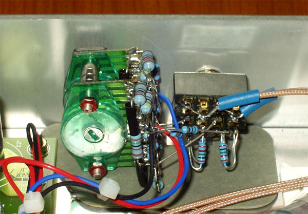 Figure 9: Finished attenuator
Conclusion
One of the major advantages of any DIY project is that it can be almost entirely customized to meet our own specific needs and requirements, allowing us to achieve a much more favorable cost-benefit ratio than would be the case if such an optimization were not done. The point of this article has been to show you precisely how to build an optimized DIY attenuator at a price that suits your budget but still fits all your specifications and does the job effectively, without compromising either the quality or usefulness of your project.
Gallery
 |
||
 |
 |
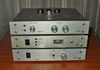 |
| Side view | Rear view | ECC86-based battery-powered preamplifier and amplifier with attenuator |
COPYRIGHT NOTICE
This material is not public domain. It is provided for your personal use only and may not be reproduced, re-distributed, re-transmitted, copied or otherwise used in any form without the express written permission of the author. You may not upload this material to any public server, on-line service, network or bulletin board without the prior written permission of the author.
The use or copying of the contents of this page, in whole or in part, for any commercial purpose is expressly prohibited.