TUBE-BUFFERED GAINCLONE (TBIGC)
(9 February 2007)
The major part of the text, figures and measurements was first released in 2003 on a do-it-yourself forum. The project was inspired by Mr. Joe Rasmussen's JLTi Tube Hybrid Amplifier, which I took a step further by designing and implementing my own power supply configuration for best performance and sound quality. The greatest challenge I faced was getting rid of the hum issues reportedly associated with the original design. The following is more or less my personal account of how I went about overcoming the problem.
At the time when I was contemplating building this hybrid gainclone amp, I was not particularly keen on throwing large amounts of money at a project that might as well have failed, for all I knew, so I decided to pile up as many of the cheap and readily available resources and parts as I could salvage from discarded equipment and stuff randomly found in the back drawers of my so-called lab.
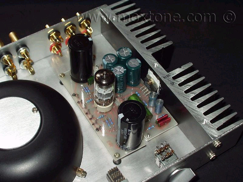
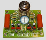
The amplifier has 5 PCBs, which were designed rather sloppily using an ancient Protel version, then drawn by hand with a permanent marker and etched with HCL and H2O2. Sorry, no PCB layout available for this one. I am afraid that my Protel design is of such an appallingly sub-standard quality that it is completely unintelligible and of no use as-is to anyone but me until I sit down and re-design the whole thing.
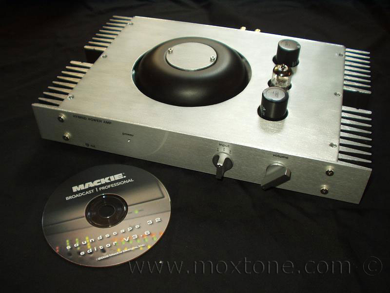
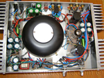
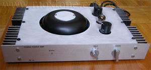
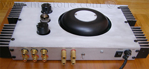
The box consists of 2mm-thick aluminum plates and 1 heat-sink on each side of the chassis. The transformer is covered by what used to be an iron lampshade with an opening at the top, which I sealed with a round piece of a brushed aluminum plate. Clever, I know. I always get double kudo points for that one. :-)
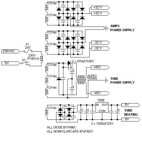
My implementation of the power supply was primarily determined by the characteristics of the transformer that I had available at hand: P=180VA and a secondary with eight 12V sections. I used 4 sections to supply LM3875, 1 to heat the tube and the remaining 3 to supply the anode current. Since the full-wave rectification could not give me 2x35V DC needed for the anode power supply (and smaller PS ripple), I decided to go half-wave instead. The trade-off resulted in a higher initial anode PS (ca 2x50V) but also a more significant PS ripple. Well, you win some and you lose some. I also used a CLC filter network and capacitor values well above the average. Since the remaining Vripple was a bit too high, I had to filter the resulting voltage (2x45V) some more with additional LC or RC stages but still keep the anode power supply over 2x35V. My experience tells me that the anode voltage of 2x35V and anode current of min. Ia=3-3.5mA are the operational minimum for E88CC tubes to work properly. If the rectifying voltage before the filters were at the minimum of 2x35V (24V AC produce only ca. 32V DC), the post-filtering voltage would be unacceptably low.
The CLC network I used consisted of 1 audio transformer with the 1:1 ratio, Rdc=25ohm, and L=80mH acting as a choke and two extra large elco caps C22,23 =6800uF (large compared to the anode current consumption of Ia=2x4mA). The resulting Vripple was thus very low - below the oscilloscope noise floor (1mV) - so that it was impossible to detect any influence of Vripple on the signal line at f=50 or 100 Hz. Such implementation also turned out to be quite convenient for protecting the tube PS from unwanted transformer load variations generated by the amplifier. However, the use of only 1 transformer normally complicates the grounding scheme considerably so less experienced designers might wish to consider using separate transformers for the tube power supply and LM3875's. I would also strongly suggest using a slightly higher initial tube PS voltage (if possible) and one or two LC or RC filtering networks.
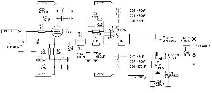
The only serious problem I encountered (and had not anticipated) in the implementation of my power supply design was significant amplitude instability that occurred when the amplifier was being switched on and disappeared once the supply voltage stabilized. This was caused mainly by a slow voltage increase on the ECC88 cathode, where the GC input cap (2u2) was connected, partly due to the slow charging of the filter caps and partly due to the slow heating of the tube. To get around this problem, I decided to add a "delay-on" circuit that would remove the noise. I had two options (IMHO): the first one was to insert a relay at the output, which would connect the speakers to the amp output once the amplitude instability disappears; the second one was to short the amp input until the instability stops. I chose the first option because the second one required two relays and it was more difficult to implement.
When I'm working on a project, I somehow always seem to find out useful new information only after I've already tightened the last screw, which is not only frustrating but also means that I would certainly do things differently with the benefit of hindsight. In this particular case, I wish I had made 2 separate mono-blocks and a bit more complex buffer circuitry.
TECHNICAL SPECIFICATIONS
Power Supply
- toroidal transformer 230V/8*12V/180VA
- output amplifier rails 2*32V DC(2*24V), two bridges with two BYW95C diodes in parallel
- caps Samsung 470uF/100V, four per channel
- tube buffer rails 2*45V (half-wave voltage doubler of 1*36Vac), two BYW95C's, CLC network, 470uF Samsung +100mH+6800uF Panasonic
- tube heating 6V DC, 4xBYW26c, 2* 1000uF Nichicon, stabilized with 7806, 1*1000uF Nichicon .
Input
- standard gold plated cinches, Alps selector 2*1in3, Preh pot 2*10klog .
Tube Buffer
- tube E88CC (NOS Tesla CH), or ECC88 (OS Siemens)
- standard metal-film resistors .
Output Amplifier
- LM 3875 - inverted setup
- gain ca 30dB
- input capacitor 2u2/250V ROE MKT, LPF 2*680pF ROE MKC, 2*47nF/160V ROE MKP
- standard metal-film resistors
- output DC offset about -5mV .
Power on Delay
- relay 10A/30VDC on output .
Input Impedance
- 10k .
Frequency Range
- 10Hz-20kHz (-1dB, -2dB)/1W/8ohm/THD=0,1%/IMD2=0.075% .
Output Power
- 36Vpp - 20W RMS (8ohm/both amps on/THD lower than 0.15% 100Hz-20kHz)
- 24Vpp - 18W RMS (4ohm/both amps on/THD lower than 0.25% 100Hz-20kHz) .
Noise Floor
- 56dBV .
Dimensions
- 330*200*40mm .
Weight
- about 5kg .
 |
||
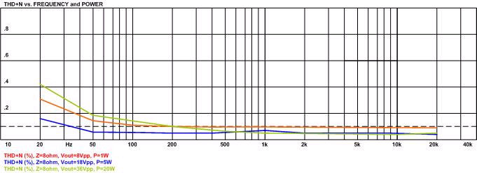
THD graph above shows decent absolute values of harmonics distortion at all output powers and frequencies. It is interesting to note that distortion falls off with the increase of power at frequencies above 200Hz and stays below 0.1%. I am guessing that there must be some kind of noise (100Hz) at the output which entered THD measurements, as a result of the imperfections of the power supply and the star-grounding method used (so the noise floor reads only -56dBV). However, the most important thing worth noting here is that the distortion is relatively constant throughout the entire frequency range, which ultimately results in very good sonic results.
The graph showing the values of individual harmonics components reveals yet another strong suite of the amplifier (again, IMHO): the values of the harmonics drop uniformly as the factor 'n' increases and this ratio is quite constant for the entire frequency range, regardless of the power or load used.
THD/output signal amplitude ratio graph, measured at 1kHz (with filters HP 400Hz, LP 80kHz), shows a constant distortion value for the amplitude range from 2Vpp to ca 40Vpp (50mW to 20W at 8ohm).
LISTENING TESTS
First off, I'd like to stress that the results of these tests should not and cannot be applied to all amplifiers of this type. They are based on my own impressions (and of some people close to me) about the absolute quality and relative listening quality of this particular amplifier in comparison with some other DIY amplifiers. Listening preferences and hearing abilities vary from person to person so if I think that a piece of equipment works really well it is by no means meant as a general truth.
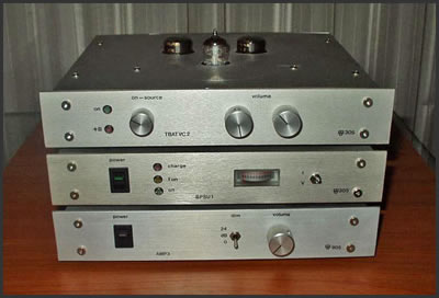
So, I built myself a hybrid version of the gainclone with my own power supply topology, using the most inexpensive and easily accessible elements and parts. I tested it with standard consumer equipment like Sony QS CD and SACD/DVD players, Sony speakers, JBL Control 1 and Control 5 speakers, and DIY 2way bass reflex speakers of a friend of mine (with Thiel C23 high and Davis Velvet 17 midbass), standard Mogami interconnections, my Aleph3 clone and my DIY tube preamp. Test material was based on the popular choice :-)) of those present and included, among others, Dire Straits Live - On the Night, Cesaria Evora's Anthology, Norah Jones's Come Away With Me, Diana Krall - The Look of Love/Live in Paris, The Crusaders - Rural Renewal, Miles Davis - Kind of Blue, Quincy Jones and His Orchestra - The Quintessence, The Dave Brubeck Quartet - Time Out, etc.
 The GC with a buffer definitely sounded better than the GC without it because the soundstage was more clearly defined, vocals were more natural, wind instruments also more defined, piano sounded less aggressive, more balanced and more integrated with the whole sound. Highest tones, which sounded aggressive and irritating on lower-quality speakers, became more pleasant and silky-sounding in the buffered version (e.g. the Pink Panther Theme). Overall, the music was much less straining to the ear and could be listened to and played almost indefinitely, even with the volume turned up very loud, without causing any fatigue. I hadn't been able to achieve any of this with the GCs I had built before (TDA or LM).
In previous shootouts, my Aleph 3 clone always beat a typical gainclone by two classes at least. However, with this tube-buffered gainclone it was a whole other story as the little half-breed turned out to be serious competition to the Aleph (they have similar distortion range). It somehow even managed to compensate for smaller speaker imperfections, which the Aleph seemed to highlight rather mercilessly although it did have a bit better control over the low-frequency range than the hybrid.
Zvonimir Vukovojac - Vuki also did a listening session, comparing 4 different GC-based amplifiers, namely: inverted LM3875 dual mono GC, noninverted LM3886 GC (with 2x2200uF/ch. filter caps), noninverted TDA7294 GC and my hybrid gainclone. The source Vuki used was a modified Marantz CD4000 and the speakers were DIY two-way Accuton C12 and C95T6 drivers. He also decided to use a Sowter attenuator-based passive preamp to eliminate the influence of different potentiometers in amps. It was a three-day listening session, which produced the following conclusions:
"The best was moamps' gainclone - very natural sounding, lots of air and great soundstage, except a little bit less control in bass than other GC's, but easily my favorite.
TDA7294 GC was second best - a touch more aggressive and a bit smaller soundstage, but better bass control.
LM3875 GC was very bright (to much for my taste) but had excellent dynamic contrast (the best of all).
LM3886 was the worst - small soundstage and aggressive, dirty highs.
I would say that HGC is the way to go!"
After such positive feedback about the sound of my amplifier (BTW, thank you Mr. Vukovojac!) and my own satisfaction with the quality of the sound and the relative simplicity of the implementation (which is one of the major advantages of hybrid gainclone concepts), I decided there was no need for a current source. In my opinion, the implementation of more complex buffer designs (e.g. higher anode PS, CS, other tube choices (like 6sn7), etc.) would make the LM3875 the weakest feature of the design and ultimately force one to wander off into contemplating other hybrid topologies and designs, such as 'tube (voltage amp)-FET(current amp)' etc. As is, this hybrid gainclone is a cute little amplifier with a surprisingly good and pleasantly balanced sound. Even with the changed and a bit more elaborate power supply design, it is quite simple to build, yet capable of beating the usual GC by a class or two. To those who tend to distrust the sound of the ECC88 tube or cathode follower as such, I can only say they should give it the benefit of the doubt as the thing is apparently capable of a surprise or two.
 |
 |
Related articles: |
|||
|
|||
|
|
|
|
 Visitors tracking data since 26 Aug. 2010
COPYRIGHT NOTICE
This material is not public domain. It is provided for your personal use only and may not be reproduced, re-distributed, re-transmitted, copied or otherwise used in any form without the express written permission of the author. You may not upload this material to any public server, on-line service, network or bulletin board without the prior written permission of the author.
The use or copying of the contents of this page, in whole or in part, for any commercial purpose is expressly prohibited.