A JOURNEY INTO THE LEGEND: THE OUTPUT CHARACTERISTICS OF THE VF 14 AND ITS SUBSTITUTES
(25 January 2014)
 Aficionados and users of vintage Neumann microphones know very well how difficult or even impossible it is to maintain these microphones in perfect operating condition over a length of time. The provision of spare vacuum tubes, the VF14 (which is used in the U47) in particular, poses a major maintenance obstacle. It is no surprise then that the scarcity of the VF14 on the market and a correspondingly whopping price tag have fuelled a frenzied search for more readily available, practical and less costly surrogates. A number of alternative solutions have been put forward, ranging from straightforward replacements of the VF14 with its FET equivalents to complex concoctions where both the original Neumann U47 power supply and the electronics inside the microphone body are redesigned so as to accommodate other suitable tubes, such as the EF14, 13, 12, etc.
As a result, the Internet has no shortage of ideas for U47 tweaks, modifications, fixes and such, often accompanied with instructions, tutorials and how to's and occasionally dished up with lavish doses of hand-clapping, swagger, bickering and controversy. However, some vital information on the most important part of the microphone – the tube – is strangely missing. Thus, for instance, you will find no data regarding the behavior of various VF14 substitutes with low anode and different power supply voltages and how they stand comparison with the VF14. Not only that, the output characteristics of the famed VF14 remain something of an enigma in themselves as it has been virtually impossible to find any online source documenting them in sufficient detail.
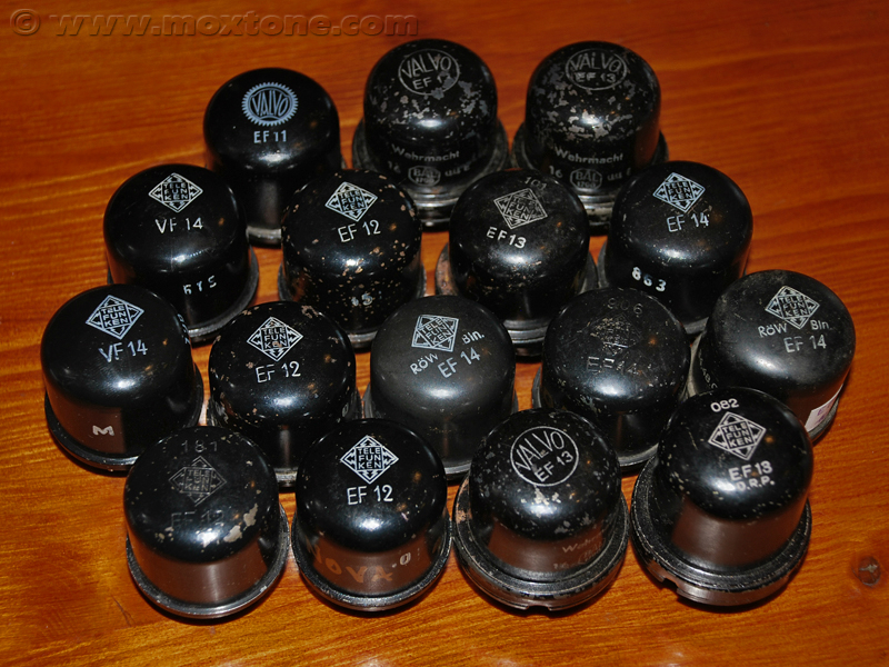
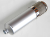
Since I happened to come by two VF14's and a dozen of EF14's, EF13's and EF12 's (pictured above; click to enlarge), I thought it would be a real shame if I missed this unique opportunity to do a comparative testing of the lot and hopefully fill in some blanks for myself, as well as others.
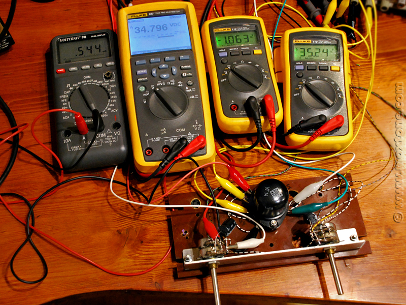
The measurements presented in this article have been averaged to obtain 'typical' values for each tube type tested. Of course, the small size of the test sample (only four tubes per type) increases the chance of error, but the results will still be useful for identifying trends, obtaining basic data and providing a ballpark idea of what to expect from these tubes. After all, some data is better than none.
VF14 MEASUREMENTS
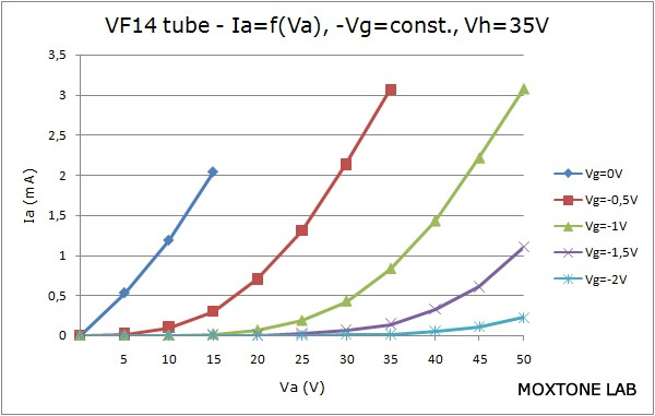
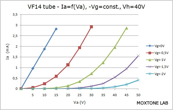
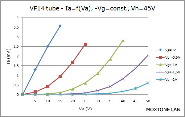
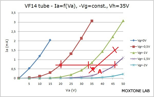
The figure below shows the output characteristics of the VF14 tube for the filament heating voltages (Vh) of 35V, 40V and 45V, respectively.
 |
 |
 |
 |
| (Click to enlarge) | |
As can bee seen, for operating point A (Vh=35V), we get:
mu=dVa/dVg=25/1=25
Ri=dVa/dIa=11/1=11kΩ .
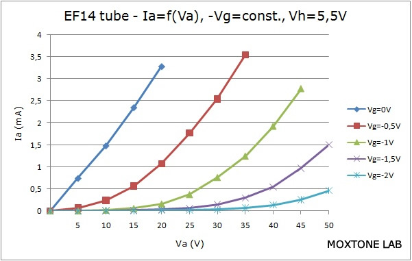
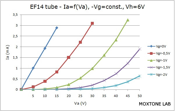
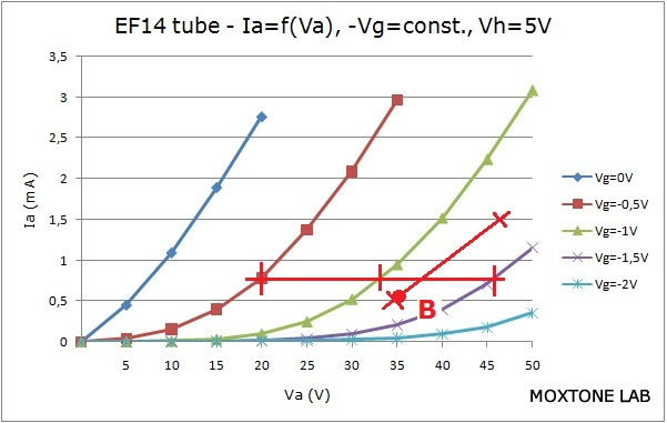
EF14 MEASUREMENTS
 |
 |
 |
 |
 |
|
| (Click to enlarge) | |
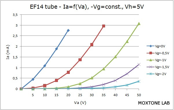
For operating point B (Vh=5V), we thus get:
mu=dVa/dVg=25/1=25
Ri=dVa/dIa=11/1=11kΩ .
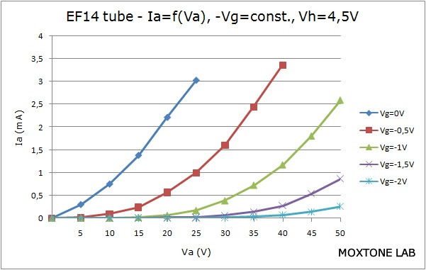
Here we can see that the EF14 measures pretty much the same as the VF14 so it is safe to conclude that the EF14 will behave the same as the VF14 in the U47 application, provided that the filament heating voltage (Vh) is lowered from the nominal 6.3V to about 4.75V. Although the information available online seems to suggest that the EF14 should be heated with 4.95V or 5.05V, these measurements clearly show that the filament heating voltage should be a bit lower than that. The only question here is whether the lower filament heating voltage can play a role in the tube's susceptibility to microphonics.
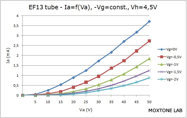
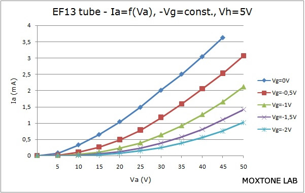
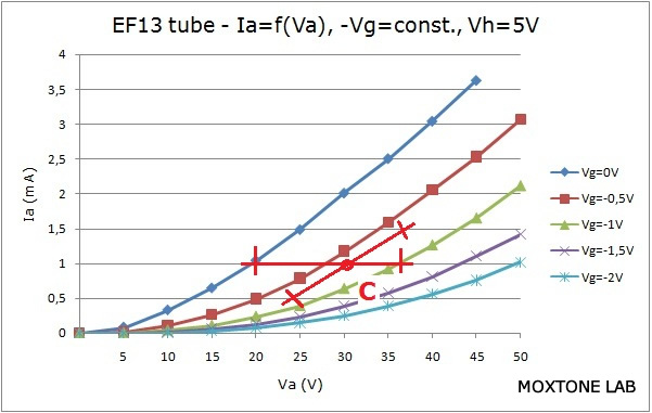
EF13 MEASUREMENTS
A first glance at the output characteristics of the EF13 reveals that it is a remote cutoff pentode, which raises a reasonable concern as to whether there is any part of its output characteristic linear enough to serve as a suitable substitute for the VF14. The measurements show that for the bias voltage (Vg) of about 1V, the EF13 is quite linear and an operating point such as the one marked C below looks like a good choice for this application.
 |
 |
 |
 |
 |
|
| (Click to enlarge) | |
For operating point C (Vh=5V), we get:
mu=dVa/dVg=18/1=18
Ri=dVa/dIa=11/1=11kΩ .
These results are very close to the VF14 and EF14 values measured earlier. Considering its low noise and the fact that I had very good results with it before in the Swank Frank project, I am inclined to believe that the EF13 may easily be the best substitute for the VF14, provided that an optimal operating point is selected, as already noted above.
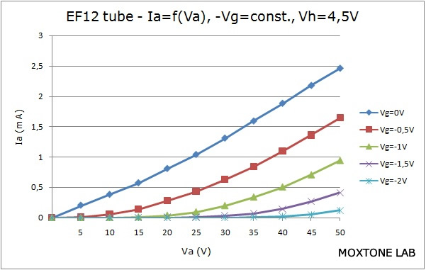
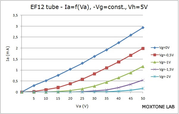
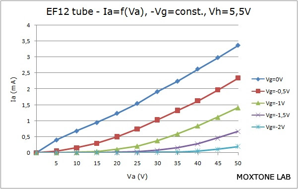
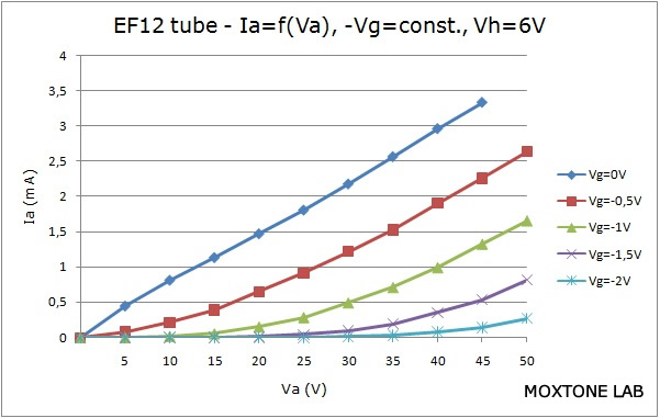
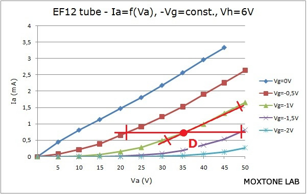
EF12 MEASUREMENTS
 |
 |
 |
 |
 |
|
| (Click to enlarge) | |
For operating point D (Vh=6V), we get:
mu=dVa/dVg=27/1=27
Ri=dVa/dIa=9/0.5=18kΩ .
There are two important points to notice here. The EF12 tube has a higher gain and a higher internal (plate) resistance (Ri) compared to the previously measured tubes. This means that another transformer, one with a higher transformation ratio than in the original U47, would have to be used. Secondly, the EF12 tube cannot be used in the "starving" mode because with low filament heating voltages, the anode current at the anode voltage (Va) of 35V would be insufficient.
CONCLUSION
The output characteristics of the test sample show that the EF14 really is, in terms of its electric properties, a direct substitute for the VF14. Reportedly, however, the EF14 has been found to be quite prone to microphonics when used in the starving mode of operation so you would be well-advised to keep that in mind as well.
The EF13 tube may have a better potential as a substitute for the VF14 than the EF14, provided that an optimum, linear operating point is chosen, as already stated earlier. Since the internal resistance (Ri) of the EF13 is similar to that of the VF14, an added plus would be its compatibility with the original U47 output transformer.
The EF12 is the worst choice of all as it cannot be used in the starving mode and it would require another output transformer.
There are other tubes with noval sockets that would be interesting to test and compare as well, such as the EF800, EF802, E80F and EF804, but that will have to wait for another occasion. Hopefully, you will find the data presented in this article a sufficiently valuable contribution to the relatively scarce body of knowledge on the VF14 and a significant help in designing microphones, particularly in understanding and evaluating different options once the VF14 wears out and fails, which it most certainly will.
|
Related articles: |
|||
|
|||
|
|||
COPYRIGHT NOTICE
This material is not public domain. It is provided for your personal use only and may not be reproduced, re-distributed, re-transmitted, copied or otherwise used in any form without the express written permission of the author. You may not upload this material to any public server, on-line service, network or bulletin board without the prior written permission of the author.
The use or copying of the contents of this page, in whole or in part, for any commercial purpose is expressly prohibited.