A JOURNEY INTO THE LEGEND: THE U47 POWER SUPPLY
(19 January 2014)
The purpose of this article is to shed some more light on the issues associated with the original Neumann NG U47 power supply that have already been touched upon in Part 1 of the mU47 microphone article series, entitled "A Journey into the Legend".
The output DC voltage of the U47 power supply is unstable and generally exceeds the nominal value of 105V DC. According to users' and technicians' reports, the voltage has been seen to go up to 130V. A very popular interpretation floating around the internet regarding the increased DC voltage levels is that they are caused by the partial short of the power transformer's primary winding due to its deteriorated insulation. As a consequence, it is suggested, the transformation ratio increases and causes the output DC voltage to go up.
Such reasoning would be plausible if we were simply to ignore the processes that went on inside the shorted part of the primary winding and their effects on the transformer's operation. In theory, but also in my own experience, such a faulted transformer would not be able to work properly for any length of time because the partial short would have caused the transformer or its primary winding to overheat and burn.
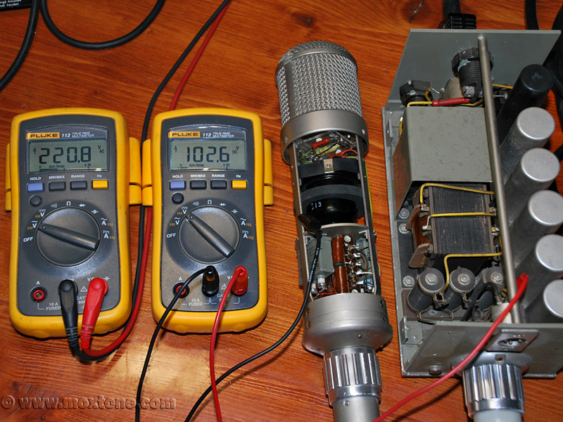
In order to test my theory, I conducted a little experiment using a power transformer equivalent to the original one from Neumann and a simulated power supply, as demonstrated in the schematic below. I shorted a small segment of the transformer's primary winding (17V) using my AC ampere meter while at the same time measuring the current of the partial short and the output voltage of the power supply. The current (Iac) of the partial short surged to a huge 4.2A while the output DC voltage not only did not increase, but actually decreased by a few volts as the power transformer reached saturation. At the same time, the primary winding became extremely hot due to the high current of the shorted segment. The experiment lasted no more than a few minutes in order to avoid the risk of destroying the transformer.
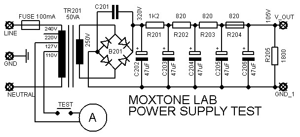
Obviously, one cannot change the transformation ratio of the transformer by shorting any part of its primary winding and get away with it without completely destroying the transformer in a matter of minutes. As already mentioned in Part 1 of the U47 article series, the correct explanation of the increased DC voltage at the output of the U47 power supply lies in the increased voltage levels of mains electricity that we have today, which the outdated U47 power supply unit just cannot handle all too well anymore. The solution to the problem would be to either use a step-down transformer at the input of the power supply in order to reduce the mains voltage by about 10-15% or to adjust the resistor values of the RC network within the power supply to accommodate the increased mains voltage.
Another popular misconception about the increased DC output voltage of the U47 power supply is that it can be fatal for the operation of the extravagantly high-priced VF14 vacuum tube as it may lead to overload and, as a consequence, precipitate the tube's rapid deterioration. This would be very logical indeed if we assumed that the operating point of the VF14 in the U47 microphone was set up at the maximum of its operating regime. In that case, any anode voltage increase by further 10-15% would take the tube outside the bounds of its operating regime and right into the jaws of its sad and untimely demise. But, is it really so?
The following table gives a comparative overview of the most important nominal parameters for the VF14 (i.e. rated values) and their actual values in the U47 microphone.
| VF 14 nom. | VF 14 - U47 | |
| Ua (V) | 250 | 35 |
| Ia (mA) | 12 | 0.55 |
| Pamax (W) | 5 | 0.00175 |
| Vf (V) | 55 | 35 |
| If (mA) | 50 | 40 |
The table clearly shows that the VF14 used in the U47 microphone runs far below its rated values. In order to see what exactly happens when the mains voltage is increased, I have measured all key operating points of the U47 for different values of the mains supply voltage. The results are laid out in the table below.
| Vm (Vac) | Vdc (V) | Va (V) | Ia (mA) | -Vg (V) | Vf (V) | If (mA) | Vbias (V) | Pa (mW) | Ptot (W) |
| 210 | 97.4 | 36.01 | 0.461 | 1.09 | 28.41 | 37.59 | 58.6 | 16.60 | 3.66 |
| 220 | 102.8 | 35.86 | 0.504 | 1.14 | 30.96 | 39.31 | 61.9 | 18.07 | 4.04 |
| 230 | 108.3 | 35.31 | 0.549 | 1.19 | 33.51 | 41.03 | 65.4 | 19.39 | 4.44 |
| 240 | 113.8 | 35.16 | 0.591 | 1.24 | 35.86 | 42.76 | 68.6 | 20.78 | 4.87 |
| 250 | 119.2 | 35.01 | 0.636 | 1.29 | 38.41 | 44.48 | 72 | 22.27 | 5.3 |
| 260 | 124.5 | 34.77 | 0.672 | 1.33 | 40.87 | 45.86 | 74.9 | 23.37 | 5.71 |
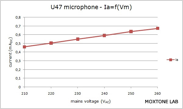
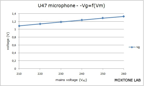
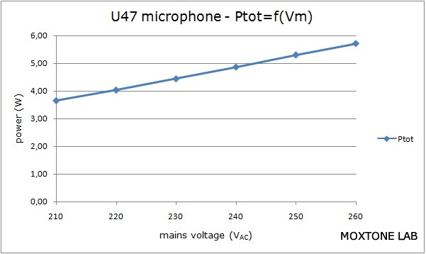
For an even clearer picture of what goes on, the above measurements have been converted into a set of graphs (below) that show the correlation between the key parameters and mains voltage variations.
 |
 |
 |
 |
| (Click for enlarged images) | |
The results of the measurements performed on the test microphone undeniably show that no tube parameters exceed their rated values when the mains voltage is increased. On the contrary, the VF14 parameters stay far below their nominal values, regardless of voltage variations. The nature of the relationship between operating point changes and mains voltage variations can be seen in the graph below that shows the output characteristic of the VF14 vacuum tube.
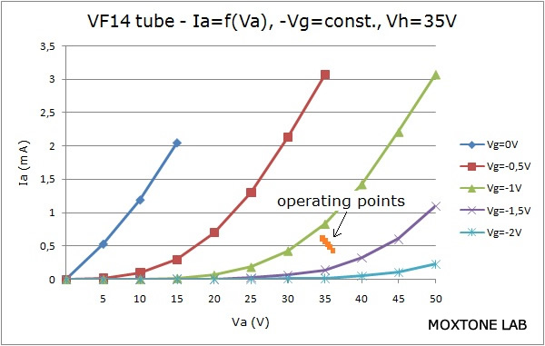
Here we can see that, for instance, when the mains voltage (Vm) is increased from 220V to 250V, the anode current (Ia) goes from 0.504 mA to 0.636 mA. In other words, for the given mains voltage increase, the anode current increases from 4% to 5.3% of the nominal value. Such a small change is surely not enough to pose any, let alone dramatic, risk to the longevity of the vacuum tube.
Another reason why the tube parameters do not change significantly when the mains voltage is increased is the forced grid bias, which serves to stabilize the operating point of the tube and reduce the impact of mains voltage variations as the negative grid bias increases with increasing mains voltage.
When the mains voltage (Vm) is increased from 220V to 250V, the filament heating power (Pf) increases from 1.3 W to 1.7 W. Rephrased, this means that the filament heating power goes from 47% to 62% of the nominal value – again, not enough to cause the purported tube deterioration.
Given all the above, it is evident that the increase of the mains voltage by about 10% cannot drive the VF14 into overload. What is more, the effects of parameter variations within 10% of their nominal values on tube longevity are hardly measurable, if at all.
However, the results reveal that there are two parameters which, although not pertaining to the tube itself, may indeed reduce the useful life of the microphone. The first parameter is the total dissipation inside the microphone body. The U47 is known to get rather warm during operation due to the heat dissipated on the resistor connected in series with the filament of the VF14 tube. From the last column in the table above, we can see that when the mains voltage (Vm) is increased from 220V to 250V, the total dissipation (Ptot) goes up from 4W to over 5W, thus significantly increasing the temperature inside the body of the microphone and consequently shortening the lifespan of the sensitive electronic components housed inside it, especially the capsule of the microphone.
 The second important parameter is the capsule's bias voltage. Its nominal value (Vbias) should be 60V whereas the table shows that for the mains voltage of 250V, we get the bias voltage of 72V! The increasing bias voltage attracts the moving diaphragm of the capsule more and more towards the backplate to the point when they can get in contact with one another, generating crackling noise. Should the bias voltage continue to increase and exceed the maximum acceptable value rated for the capsule, permanent damage is done and you can bid your capsule adieu. Even when the bias voltage does stay within acceptable limits, the frequency characteristic of the capsule will change, progressively suppressing the low-frequency part of the spectrum as the bias voltage increases. This may also be the main reason why many U47 users on various online discussion boards report that their microphones tend to sound better when supplied with higher mains voltages. In my opinion, the change in the capsule's bias is the most important consequence (whether for good or for bad) of mains (and DC) voltage variations and the most important cause of differences in the sound of the microphone, depending on the mains supply it is connected to.
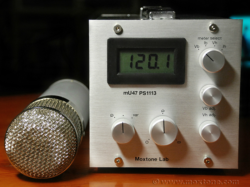
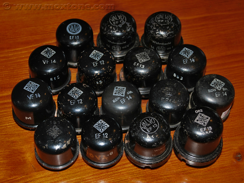
As can be seen, there is no evidence that increased mains voltage levels lead to the premature deterioration and failure of our dearly precious VF14 tube. However, increased mains voltage levels do have a quite significant effect on some other parameters of the microphone. So, to those of you out there who use their U47 as a work tool rather than a collectible showcase piece waiting for the highest bid, I would suggest to consider replacing the original power supply with something like shown in the previous article on the mU47 variant of the microphone, where all critical parameters can be easily controlled and set to desired values. Such a solution would eliminate many microphone maintenance headaches, reduce the risk of microphone/tube failure and, at some point later down the road when the VF14 is no more, make the transition to alternative solutions (EF14, 13, 12, etc.) a much more painless experience in terms of both time and money.
|
Related articles: |
|||
|
|||
|
|||
COPYRIGHT NOTICE
This material is not public domain. It is provided for your personal use only and may not be reproduced, re-distributed, re-transmitted, copied or otherwise used in any form without the express written permission of the author. You may not upload this material to any public server, on-line service, network or bulletin board without the prior written permission of the author.
The use or copying of the contents of this page, in whole or in part, for any commercial purpose is expressly prohibited.